
Tags: TEC thermal management, thermoelectric cooling, heat pipe heat sink, skived fin, high-power temperature control.
1,Why do we run this data comparison?
You can learn how to design TEC heat sinks from this article, and understand when to select heat pipe heat sinks versus skived fin heat sinks. This piece targets engineers and senior buyers. All data and theoretical results in this article come from our real physical tests, making it highly valuable for reference.
After working on TEC projects for a long time, we’ve learned a key engineering rule: when the temperature difference ΔT between the cold and hot side equals zero, the TEC reaches its maximum rated cooling capacity. Meanwhile, the total heat to be dissipated from the hot side also hits its peak, which makes this the harshest working condition for TEC heat dissipation.Many high-power temperature control projects fail to meet the cooling target, not because the TEC chip itself is defective, but because the hot-side heat sink cannot handle the full heat load.
2,Simulation data and test conditions
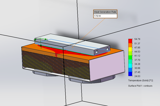
We built a physical comparison test for a 170W cooling capacity TEC module. Two heat sink designs were tested under identical fan settings and ambient conditions, to compare performance and suitable application scenarios.The test module consists of 4 pcs of 45×45×3.5 mm TECs, powered at 12V, with a rated cooling capacity of 170W under ΔT=0. Solution 1 uses a heat pipe through-fin heat sink, fitted with 10 pcs of 9 mm OD heat pipes. Heat is quickly transferred to the fin array by heat pipes, with two 120×120×38 mm, 2500 RPM axial fans for forced air cooling. Solution 2 is our optimized one-piece skived fin heat sink. The base and fins are formed in a single process, eliminating multiple contact thermal resistances introduced by heat pipe assembly. The fan setup remains exactly the same to keep test variables consistent.
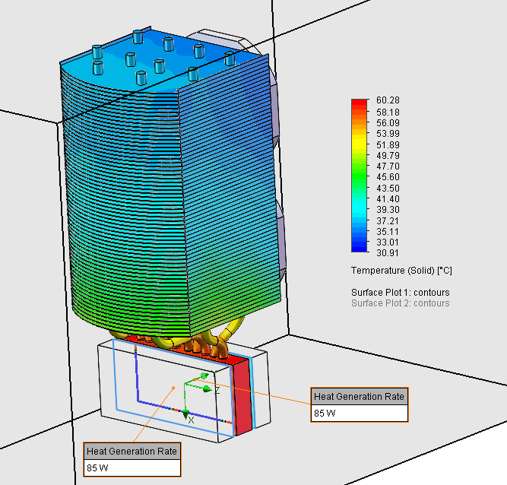
Once steady state is reached, we recorded cold-side temperature: Heat pipe through-fin design: 60.28°C Skived fin design: 54.79°C.Under the same test conditions, the monolithic skived fin heat sink delivers a lower cold-side temperature and better thermal performance. That said, I would not conclude that skived fin is always superior. Engineering selection should never rely on a single temperature reading.
3,How to Design a TEC Cooling Module
If the overall assembly is compact with tight space constraints, or the heat source and fin area cannot be arranged on the same plane and heat needs to be moved to another zone, the heat pipe solution is the better fit. Heat pipes feature ultra-high equivalent thermal conductivity for long-distance heat transport, and it is a proven, reliable option for space-limited products.
On the other hand, if there is no strict limit on product dimensions and enough space is available for a larger heat exchange area, the one-piece skived fin structure shows its strengths. Without intermediate contact thermal resistance from assembly, the thermal path is shorter for better cooling performance. It is also simple to manufacture with stable yield, ideal for mass production.
For high-power TEC thermal management, the final solution depends on the whole system layout. Go with skived fin when space allows; choose heat pipes when space is tight and heat relocation is required. Evaluate layout, heat transfer distance and cost at the early design stage, so you avoid thermal issues after prototype build.When you work on TEC cooling, do you mostly face tight space limits, or can you design a large air-cooled heat sink freely? Feel free to share your experience.For us, the parameters generally required to design a TEC module are as follows:
*Operation Voltage: 12 ,24 or48VDC;
*Power rating: (TEC power, electrical input power, cooling capacity and other related power indicators?)
Filling tank volume: ?L;
Climate type: N, SN;
Design life: 5years or 10 years;
Production dimension: L*W*H;
Product net weight:(Weight constraints for the product, for example in medical applications)
Operation environment: ?°C, Humidity ?%
Control temperature: ?°C
Fan Noise level:
Recording location: Front of unit, 1m and fan centerline Operating mode: Both fans at 100%, Both pumps running Criteria: ≤ ?dB(A)
Cooling Fan
(eg:)Rated Voltage DC12VDC, Rated Current: 0.12A
Rated Speed 1700+/-10%RPM
Fan Noise: Under 30dB
Life time >50000 hours
Heating performance:
(eg:Ambient temperature 25°C, Setup: unit plugged into 1.5m pigtail, Water temperature: 25-50°C, Time duration, Dual zone: 15minutes Time duration, Single zone: 10minutes)
Water block(eg:)
- Flow rate: connect with a standard 6L water pump for testing
requiring flow rate greater than 4L; - Put the water block into the water, maintain the ambient temperature of -18°C for 6 hours, then the temperature rises to 100°C and maintain it in 100°C water for 2 hours, for one cycle, test cycles. There should be no falling off, bulging, leaking water other phenomena everywhere in the workpiece;